Building Railways
The first main feature of Railway Operation Simulator is the process of creating railways.
The option to enter railway building mode is from the mode menu. It is possible to start from a blank canvas, or edit an already loaded railway. On the top row of this menu you can select to edit the elements, add text, name stations and locations, set the element distance and speed, change the signal type and add user graphics.
All track elements are placed on a grid, with a maximum of one track element per grid square. It is possible for text and user graphics to be placed anywhere on the screen. (Not aligned with the grid.)
Once the elements have been placed and locations have been named, the railway can be linked and made into a .rly file. Although not necessary, adding speed and distance information to elements is highly recommended, especially if the railway reflects the real world. This is because it will mean a timetable will fit the railway correctly.
The user also has the option to add Preferred Directions to the railway, this will allow any operator to use the preferred and automatic routing when operating the railway.
Tools and Features
Element Editing Tools
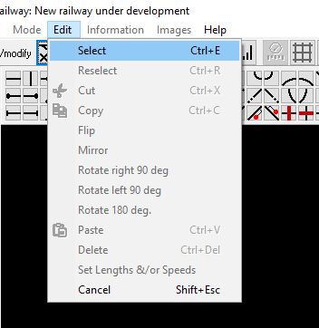
As well as placing track pieces on the grid, the editing interface has a few additional tools. These are accessible from the Edit menu at the top.
The main option is the select tool, once selected you can drag this over the canvas and select any number of elements. After an area is selected, the other options are unlocked.
- Cut - Removes the selected track and allows it to be pasted elsewhere.
- Copy - Copies the selected track and allows it to be pasted elsewhere.
- Flip - Flips the selected track so that the top becomes the bottom and vice versa.
- Mirror - Mirrors the selected track horizontally so that the right becomes the left.
- Rotate - Rotates the selected track pieces by the specified amount.
Additionally to this, when a blank area is selected, the user can fill it with any element by selecting it from the top.
Location Naming
For a railway to be saved as a .rly file, all locations (connected stations and 'blue' non-station locations) must be named. This is done using the "Set or Change Station Names" by selecting the location and entering a name.
Setting Distances and Speeds
Although not strictly necessary, setting the distances and speeds to each element is very important to ensure that timetable is accurate, especially on a route imitating a real-life route.
This is done using the "Check & Set track element lengths & speed limits" tool, and can only be completed on a successful completion of the route, although this can be done before locations are named.
When setting distances and speed limits, a section of track can be selected, and a combined length and speed limit can be entered. The length is split equally between all track elements in the selection.
User Graphics
Images can also be added to the route. The images must be accessible to the program, so must be included when sharing the route. User graphics are generally stored in the Graphics folder in the railway root directory. Track can be placed on top of user graphics.
Connecting Gaps
If you have used gap elements in your railway, you will need to connect them before you can save it as a .rly file. This is done using the "Connect Gaps" tool.
The tool will highlight one gap element and the user will need to click on the corresponding gap element. This will continue until all gap elements are connected.
Preferred Directions
Although not required, the preferred directions tool is highly recommended. It will allow the use of the green and blue routing types when operating the route. This is because they rely on knowing which direction is the best to get between any two signals.
This tool is available from the Mode menu, and the route must be saved and have a successful completion to use the tool. It works by selecting multiple track elements, and the preferred direction will run along the selected route. Confirm your route using the add button in the menu.
Track Element Types
Basic Track Elements
The program includes several basic track elements, these include straight tracks, 90 and 45 degree curves and track crossings.
Junctions
There are both junctions in both directions in 90 and 45 degree forms. These elements have a speed and distance value both for the straight track and the curved section.


